
Altitude plays a critical role in cold room design and operation. As altitude rises, atmospheric pressure drops, altering the thermodynamic behavior of both air and refrigerants. If not accounted for, these changes can lead to reduced cooling capacity, inefficient energy use, and compromised temperature control.
In this article, we explore the mechanisms by which altitude impacts cold room performance, highlight design considerations, and operational adjustments.
1. Atmospheric Pressure and Refrigeration Basics
1.1. Atmospheric Pressure Variation
- Sea Level Baseline: At sea level (0 m), standard atmospheric pressure is approximately 101.3 kPa (14.7 psi).
- Elevation Effect: With every 1,000 m increase in altitude, atmospheric pressure drops by roughly 11–12 kPa. For example:
- 1,000 m: ~89.9 kPa
- 2,000 m: ~79.5 kPa
- 3,000 m: ~70.1 kPa
This reduction in pressure has direct consequences on both the refrigerant cycle and the condenser/evaporator performance.
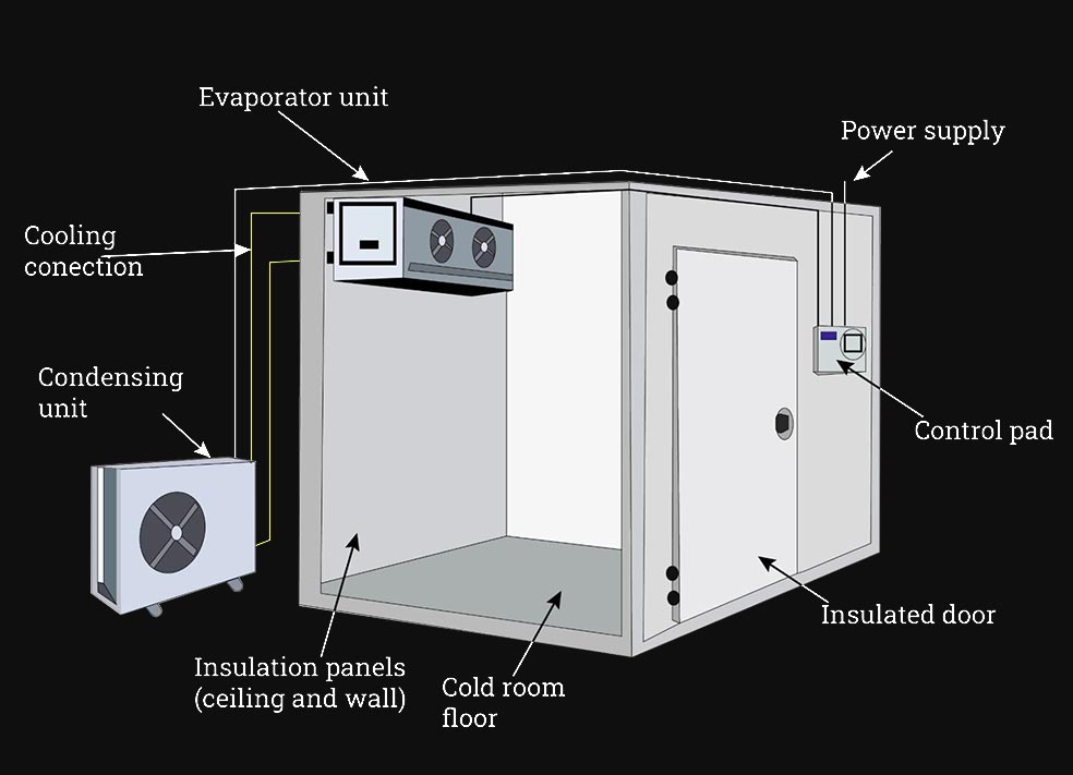
1.2. Refrigeration Cycle Overview
- Evaporator: Absorbs heat from the cold room by evaporating liquid refrigerant at low pressure.
- Compressor: Increases refrigerant pressure and temperature, preparing it for condensation.
- Condenser: Rejects heat to the ambient air (or water), condensing the refrigerant back to liquid form.
- Expansion Device: Lowers refrigerant pressure and temperature before it enters the evaporator.
At higher altitudes, lower ambient pressure alters both the boiling point of the refrigerant and the condenser’s ability to reject heat.
2. Thermodynamic Effects of Altitude
2.1. Lower Boiling and Condensing Temperatures
- Boiling Point Depression: Reduced atmospheric pressure lowers the boiling point of liquids, including refrigerants. For a given pressure, the refrigerant boils (evaporates) at a lower temperature than at sea level.
- Refrigerant Saturation: In the condenser, refrigerant saturation pressure is tied to ambient pressure. Lower ambient pressure means refrigerant condenses at a lower saturation temperature for the same pressure.
Implications
- Reduced Temperature Lift: The temperature difference (“lift”) between the evaporator (cold room) and the condenser (ambient) may increase or decrease depending on system design. A smaller lift can reduce compressor work; a larger lift increases it.
- Subcooling and Superheat Adjustments: Control settings for subcooling (liquid refrigerant below saturation) and superheat (vapor refrigerant above saturation) need recalibration at altitude to prevent liquid carryover or compressor flooding.
2.2. Air Density and Heat Transfer
- Air Density Reduction: At 2,000 m, air density is about 80% of that at sea level. Reduced air density results in fewer molecules available to transfer heat in the condenser and evaporator coils.
- Heat Transfer Coefficient: With less dense air, convective heat transfer performance deteriorates. Fans and coils must work harder or be resized to achieve the same heat rejection/absorption rates.
3. Impact on Cold Room Components
3.1. Compressors
- Reduced Mass Flow: Lower suction-side pressure causes a reduction in mass flow rate of refrigerant vapor into the compressor. This can diminish cooling capacity.
- Increased Discharge Pressure: In some cases, the compressor may see higher discharge temperatures when condensing at a lower pressure, affecting lubricant viscosity and component longevity.
Operational Tip: Some compressor manufacturers offer high-altitude kits (e.g., modified valves or lower compression ratios) to maintain capacity at elevations above 1,500 m.
3.2. Condensers
Air-Cooled Condensers:
- Fan Performance: Fans generate less airflow in thinner air. As a result, condenser coils may not reject heat efficiently, leading to higher condensing pressures if not properly adjusted.
- Coil Sizing: Larger coil surface area or additional fan capacity is often required at higher elevations.
Water-Cooled Condensers:
- Heat Exchange Efficiency: While water-cooled systems are less sensitive to air density changes, the evaporative cooling towers or heat rejection units still rely on ambient air; therefore, adjustments may still be necessary in very high altitudes.
3.3. Evaporators
- Frosting Behavior: With lower ambient pressure and humidity, the rate and distribution of frost on evaporator coils can change. In some dry, high-altitude regions, frost may build more slowly but can melt into localized wet spots, affecting defrost cycles.
- Airflow Considerations: Evaporator fans experience similar reductions in airflow in thin air, potentially causing uneven cooling or stratification if fan speeds aren’t increased or blade pitch adjusted.
3.4. Controls and Refrigerant Charge
- Pressure Switch Settings: Both high-pressure and low-pressure cutouts need recalibration for the reduced suction and discharge pressures.
- Thermostat Calibration: Thermostats and pressure-based sensors should be checked against calibrated reference instruments, as their readings can be skewed by lower pressure.
- Refrigerant Charge: In some cases, a slightly reduced refrigerant charge helps maintain proper evaporator coverage and reduces the risk of flooded return to the compressor. However, this must be balanced against capacity requirements.
4. Design and Engineering Adjustments
4.1. System Sizing
- Capacity Correction Factors: Many equipment manufacturers provide correction charts. For instance, at 2,000 m, a compressor unit rated at 100 kW at sea level may only deliver ~85 kW. Designers specify oversizing or select equipment with higher nominal capacity.
- Condenser Sizing: Increase the face area of air-cooled condensers by 10–15% for every 1,000 m above 1,500 m elevation, or upgrade to dual-fan arrays to compensate for reduced air density.
- Fan Motor Selection: Use motors rated for higher RPM at lower torque to maintain airflow in thinner air. Variable frequency drives (VFDs) can help fine-tune fan performance.
4.2. Insulation and Building Envelope
- Insulation R-Values: While altitude itself does not directly affect insulation properties, colder ambient temperatures at high elevations often necessitate higher R-values to prevent frost heave or excessive thermal infiltration.
- Air Sealing: Reduced air density can exacerbate infiltration; seal all gaps meticulously to keep cold air in and humid outdoor air out, particularly in regions with significant diurnal temperature swings.
4.3. Defrost Systems
- Defrost Scheduling: Thinner air often contains less moisture, potentially reducing frost accumulation rates. Programmable defrost cycles can be lengthened or shifted to off-peak periods to conserve energy.
- Hot-Gas Defrost: In ultra-high elevations where electric defrost coils have reduced heat transfer, hot-gas defrost systems provide more reliable defrosting.
4.4. Refrigerant Selection
- Low-Pressure Refrigerants: Some refrigerants perform more predictably at high altitudes. For example, R-404A or its low-GWP alternatives (like R-448A or R-449A) maintain fairly consistent performance down to 0 °C evaporating temperatures.
- Critical Point Considerations: At very high altitudes (above ~3,000 m), the critical point of certain refrigerants approaches ambient condensing temperatures, potentially reducing subcooling margins. In these scenarios, refrigerants with higher critical pressures (e.g., R-410A) can be preferable if the design allows.
5. Case Study: Cold Room at 2,500 m Elevation
5.1. Baseline Conditions
- Location: Mountain town at 2,500 m (≈8,200 ft).
- Typical Ambient: 15 °C summer average, 5 °C winter average. Humidity ~40%.
- Target Cold Room Temperature: –18 °C for frozen goods storage.
5.2. Equipment Selection
- Compressor: Selected a model with 120 kW nominal capacity at sea level, providing approximately 100 kW at 2,500 m (correction factor ≈0.83).
- Condenser: Air-cooled, with a 20% larger coil area than sea-level equivalent, dual sequential fans, and VFDs for precise airflow control.
- Evaporator: Standard coil, but with a 10% higher airflow rate (using higher RPM EC fans) to compensate for reduced air density.
- Refrigerant: R-448A, chosen for its stable performance near the critical temperature at moderate high altitudes.
5.3. Control and Commissioning
- Pressure Switches: Calibrated against a reference gauge; high-pressure cutout set to 30 bar, low-pressure cutout to 2.3 bar (instead of sea-level 33 bar and 2.6 bar respectively).
- Thermostats: Electronic temperature sensors installed at multiple heights within the room to detect stratification.
- Defrost: Hot-gas defrost cycle programmed every 48 hours, extended by 30% compared to sea-level recommendation, due to slower frost formation.
5.4. Performance Outcomes
- Cooling Capacity: Achieved –18 °C within 4 hours of a full-load startup, comparable to sea-level benchmark at –18 °C in 3.5 hours (slightly longer due to reduced capacity).
- Energy Consumption: Electrical usage increased by ~12% due to larger fans and longer compressor run times. However, consumption remained within acceptable operational budgets.
- Temperature Stability: Variations within ±0.5 °C, indicating successful control despite altitude constraints.
7. Summary of Key Adjustments by Altitude
| Elevation Range | Pressure Reduction | Compressor Correction | Condenser Adjustment | Fan/Coil Changes |
|---|---|---|---|---|
| Sea Level (0 – 500 m) | 0–6 kPa | None | Standard | Standard |
| Moderate (500 – 1,500 m) | 6–17 kPa | 5–10% Capacity Drop | +5–10% Coil Area or VFD Fans | +5–10% Fan Speed |
| High (1,500 – 3,000 m) | 17–31 kPa | 10–20% Capacity Drop | +10–20% Coil Area, Dual Fans | +10–15% Fan Speed, Higher RPM EC Fans |
| Very High (> 3,000 m) | >31 kPa | >20% Capacity Drop | +20–30% Coil Area, Specialized Kit | Variable speed to compensate thin air, possible ducted air assists |