
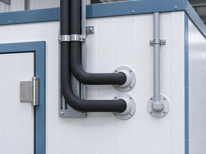
A cold room penetration needs a continuous seal at the panel and a suitable closure around the service passing through it. For a LINBLE modular room, put the cable gland, conduit or insulated pipe on a coordinated penetration drawing before anyone drills a panel. Give the installer a section showing the sealed plane, the fitting, support and the space needed to finish and inspect the work.
Which Holes Should Be Drawn Before the Panels Arrive?
Make a register for refrigerant lines, drain lines, power, control cables and sensors. Record the room ID, panel face, hole center, service dimensions and the installer responsible. Lay the register over the panel drawing to check that sleeves will clear locks, joints, structure and door reinforcement.
Use the LINBLE cold room panel range to establish the selected panel construction and assembly method. Confirm any allowable locations with the panel designer. A hole that avoids a visible seam can still cut into a lock or the reinforced part of a panel if the shop detail is missing.
The NIBS enclosure commissioning guideline discusses detailing sleeves and sealing mechanical and electrical penetrations. For a cold enclosure, apply that principle to both the service and its interface with the intended air and vapor control layer. The assembly detail should specify how the connection is made before the lining hides it.
Can Several Services Use One Opening?
Sometimes a coordinated multi-service system is appropriate, but the assembly must suit the cable and pipe sizes, environmental exposure and any rating required. The individual routes still need reliable seals and service access. An oversized hole packed around several different materials is difficult to inspect once it is covered.
Check whether adding one cable later would disturb the seal around a live service or the insulation around a refrigerant line. If expansion is planned, use a spare sealed pathway on the approved design. Record how it will be closed now and how the next installer can put it back into service.
How Should Cables and Conduits Cross the Panel?
Specify a gland or other approved fitting that suits the cable size and the expected exposure. Seal its attachment to the panel as shown on the drawing, and make sure the service has the required strain relief and support. The visible fitting can look well seated even when the path behind it remains open.
Conduit deserves particular attention. It can carry air internally if the bore is open between spaces, even if the outside is sealed at the wall. Ask the electrical designer to specify the appropriate sealing arrangement and access for inspection under the local installation requirements.
| Service | Interface to Show | Check Before Closing |
| Single cable | Gland or entry fitting, attachment and seal to panel | Cable size matches fitting, closure is continuous and cable is supported |
| Conduit | Panel-to-conduit detail and any required internal seal | Approved method reaches the intended control plane |
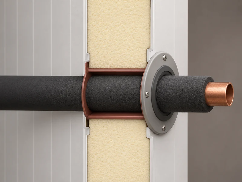
| Insulated refrigerant pipe | Sleeve, pipe insulation and closure to the panel | Pipe insulation and its vapor seal continue through the detail as designed |
| Drain | Sleeve, service support and route toward discharge | Required fall, service access and appropriate protection at the transition |
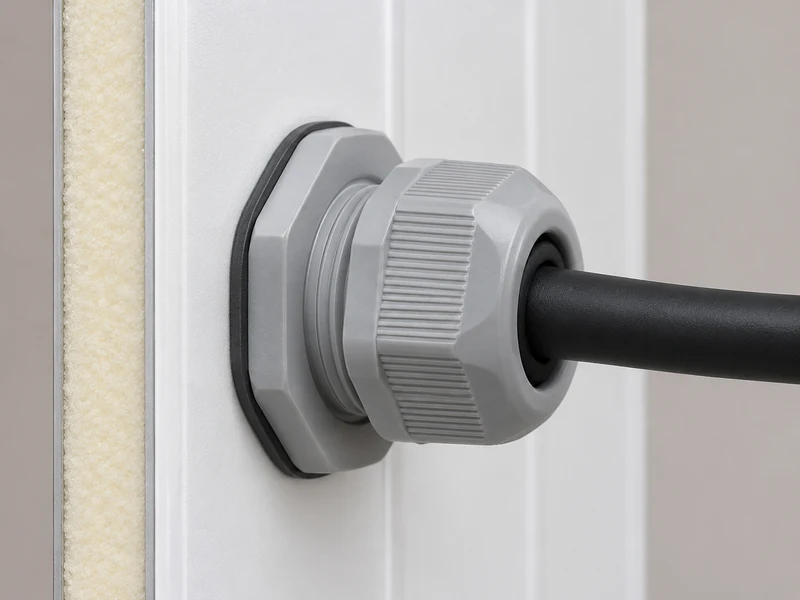
Use the LINBLE electrical requirements guide when the penetration carries room power or control wiring. Agree the route and termination points with the site electrician so field changes do not leave unused holes. Cable entry should be coordinated with washdown conditions and with any enclosure ratings that apply.
How Do You Keep a Pipe Penetration From Sweating?
Design the pipe insulation and wall seal as connected layers. The selected sleeve and closure should allow the required pipe insulation and its vapor seal to pass through or reconnect in accordance with the approved detail. Support the pipe independently where the project requires it so normal movement and weight do not work the seal loose.
The ASHRAE refrigerated-facility design chapter explains the importance of air and vapor control continuity at cold-envelope junctions. At a pipe sleeve, the drawing should show which face or layer carries the principal seal, how it connects to the pipe assembly and how any sanitation finish is completed. Review the conditions on both sides when the wall is between two controlled spaces.
For example, a suction line that leaves a freezer through a humid service corridor can drip where its insulation ends at the sleeve. Covering the face with trim may hide the first wet spot without restoring the insulation or its vapor seal. The coordinated detail needs to address the cold surface and the air path at the same time.
What About the Evaporator Drain?
Show the exit height, slope and discharge location before the panel is cut. Verify which drain sections need insulation, heat or other protection under the approved design, especially where the route passes through colder space. Leave access to the sections that require inspection and cleaning.
The equipment position and the panel opening should agree on a single section. In a LINBLE modular cold room, a shift in the cooler position can move its outlet beyond the intended sleeve and lead to an extra cut. Coordinate any late change with the installer before the new route is opened.
When Does the Penetration Need to Move?
Move it on the drawing if the installer cannot reach the seal or if the service conflicts with the intended panel connection. Consider a drain sleeve planned directly over a wall-to-floor trim. Shifting it far enough to expose the closure for inspection may also change the drain slope or support points, so the refrigeration and enclosure details should be revised together.
On a cable route, confirm whether the fittings can be tightened after equipment is mounted. A gland drawn neatly behind a controller may have little wrench clearance. Resolve the position before cutting and check the modified route against the enclosure and the cable’s support requirements.
Record unused sleeves and how they are capped in the same register as active ones. During construction, an open spare often disappears behind equipment or a cover plate. The inspection record should locate the closure so future installers can identify it without disturbing adjacent seals.
Who Checks the Detail Before It Is Covered?
Assign the inspection to a named person and set a hold point after the services are supported and before trim conceals the seal. Check that the openings match the register, the sleeves are stable and the specified materials are visible where they should be. Take a wide photo locating the service and a close photo showing the closure.
If the service is expected to move with temperature or maintenance, check how the specified detail accommodates that movement. After initial cooling, look at the accessible faces for dampness, gaps or signs that the pipe load is pulling on the fitting. Compare observations with the agreed acceptance procedure and investigate any recurring mark before closing the item.
Compare the joint alignment to the surrounding installation. LINBLE’s guide to modular panel fit explains why base support and alignment matter before adjacent work is finished. Where a field hole falls close to a panel connection, resolve the fit before relying on the penetration trim to disguise it.
At handover, use the cold room commissioning checklist to record what was inspected and any open items. Keep the final penetration register with the room drawings so the next service team can locate hidden sleeves and identify the approved way to add or replace a service.