
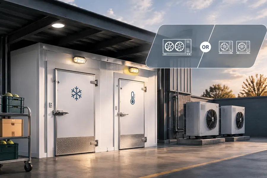
A walk-in cooler freezer combo can share an insulated footprint without sharing a refrigeration circuit. For a chilled compartment at +3°C and a frozen compartment at −20°C, the important question is whether one compressor can serve both efficiently—or whether independent medium- and low-temperature systems are the better investment.
For most small commercial dual-temperature cold rooms, two independent refrigeration circuits are the simpler starting point. A shared system is possible, but the supplier must demonstrate how it manages different evaporating pressures, defrost cycles, and simultaneous cooling loads.
First, Find Out What “One Unit” Actually Means
A quotation for “one condensing unit” can describe three very different arrangements:
| Configuration | What Is Shared? | What Buyers Should Expect |
| One compressor, two evaporators | Compressor, condenser, and common suction circuit | Lowest-temperature duty influences both zones; specialized pressure and capacity control is needed |
| One outdoor cabinet, two independent circuits | Mainly the cabinet or mounting space | Separate compressors and controls can preserve different temperature duties |
| Two separate condensing units | Neither refrigeration circuit is shared | Independent servicing and operation, but more equipment and installation space |
Count compressors, refrigerant circuits, and suction groups, not simply outdoor cabinets. Two indoor evaporators and two thermostats do not by themselves make a system independent.
Why the Cooler Should Not Always Run at Freezer Pressure
A freezer needs a colder evaporator than a chiller. Consider an illustrative design:
- Cooler: +3°C room air, approximately −5°C evaporating temperature.
- Freezer: −20°C room air, approximately −27°C evaporating temperature.
These are explanatory operating points, not LINBLE model ratings. Actual values depend on coil selection, humidity requirements, and refrigerant.
If both evaporators return to one common suction header, the compressor generally operates near the pressure required by the colder freezer. An evaporator pressure regulator (EPR) can hold the cooler coil at a higher pressure, but gas then passes into the lower-pressure suction line. The compressor does not recover the efficiency advantage of operating the cooler load at its naturally higher suction pressure.
ASHRAE’s guidance on multi-evaporator refrigeration explains why common-suction systems are governed by their coldest evaporators. Likewise, an industrial refrigeration energy-audit guide hosted by Oregon State University recommends grouping loads with similar suction requirements.
A multi-compressor system with distinct suction groups can address this issue. That is materially different from connecting two temperature zones to one ordinary low-temperature condensing unit.
What a 30 m³ + 30 m³ Combo Suggests
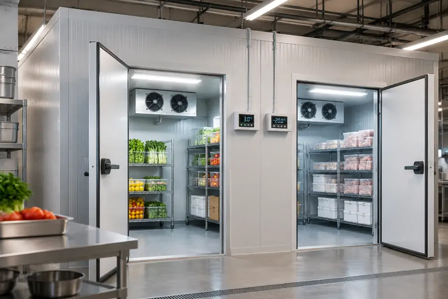
Imagine a restaurant or supermarket with two adjoining 30 m³ compartments. LINBLE’s published preliminary selection ranges give the following starting points:
| Compartment | Target Room Temperature | Preliminary Condensing-Unit Reference | Typical Insulation Guidance |
| Walk-in cooler, 30 m³ | +3°C | 2–3 HP for a 20–40 m³ chiller | 75–100 mm |
| Walk-in freezer, 30 m³ | −20°C | 3–5 HP for a 20–40 m³ freezer | 100–150 mm |
These ranges come from LINBLE’s condensing-unit sizing guide. They are not a basis for adding the horsepower figures and ordering a single 5–8 HP compressor. Horsepower is a motor rating, not a guarantee of delivered cooling at two different evaporating temperatures.
The final selection needs two separate heat-load calculations covering transmission, product pulldown, door infiltration, fan and lighting gains, and freezer defrost recovery. Then compare equipment capacity in kW at the specified evaporating and condensing conditions, including the hottest expected outdoor conditions.
Equipment matching matters too. LINBLE lists DL chiller evaporators with 2.1–152 kW capacity and DD freezer evaporators with 1.4–105 kW capacity, across their respective model ranges. Select from the cold room evaporator range by the actual duty, airflow, and frost load, rather than choosing two coils of equal size.
Defrost Is Where Shared Circuits Become Complicated
Cooler and freezer evaporators usually need different defrost logic. A medium-temperature cooler may use off-cycle defrost, while a low-temperature freezer typically requires electric or hot-gas defrost. ASHRAE’s commercial refrigeration guidance describes that distinction.
With one shared compressor, the freezer’s defrost cycle must not inadvertently interrupt required cooler cooling or cause uncontrolled refrigerant movement. The design should show:
- Branch isolation: Which solenoid valves stop refrigerant flow to the evaporator being defrosted?
- Fan and drain control: When do freezer fans stop, drain heaters operate, and fans restart?
- Pressure management: How do the compressor, EPR, and pump-down controls react while one zone calls for cooling?
- Recovery: Can both compartments return to their setpoints after defrost and heavy door traffic?
Separate circuits simplify this sequence because the cooler does not depend on the freezer’s refrigerant controls. They do not remove the requirement for suitable temperature alarms and defrost configurations.
Judge Capacity at 2 p.m., Not Just on a Quiet Night
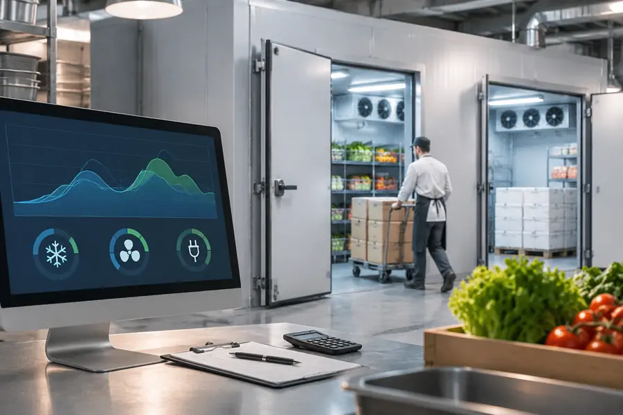
Consider a food-service site where the cooler door opens repeatedly during receiving and meal preparation while the freezer stays relatively stable. Later, the freezer receives new stock while the cooler load falls.
A single compressor selected for the combined peak may have too much minimum capacity when only one compartment calls for cooling. Poor staging can produce frequent starts and temperature swings. Variable-capacity controls can help, but they must be specified and proven rather than assumed.
Ask the designer to test three conditions:
- Both zones at peak load: High ambient temperature, expected deliveries, and simultaneous cooling demand.
- Cooler-only demand: Frequent door openings while the freezer is already at temperature.
- Freezer recovery: Warm-air infiltration or post-defrost pulldown while the cooler has little demand.
To support energy consumption comparisons, ask for projected annual kWh figures covering compressors, condenser fans, evaporator fans and defrost heaters. Do not compare equipment prices or nameplate HP alone.
When Sharing Equipment Makes Sense
A shared refrigeration arrangement is worth engineering when several cold rooms operate together, outdoor equipment space is limited, or a properly designed central plant already exists.
But the distinction matters:
- One compressor and a common low-temperature suction: Usually a weak default for one cooler plus one freezer unless a detailed design and running-cost study justify it.
- Two independent circuits in one cabinet: A useful space-saving option if service access, refrigerant isolation, and electrical separation are genuinely provided.
- Multiple compressors with separate suction groups: Potentially suitable for larger multi-room installations with appropriate controls, commissioning, and maintenance support.
- Two standalone systems: Often the practical choice for a restaurant, small distribution room, or business needing straightforward fault isolation.
An independent compressor does not guarantee uninterrupted storage. A shared power supply, condenser location, or control panel can still create common failures. Check those dependencies before calling either option “redundant.”
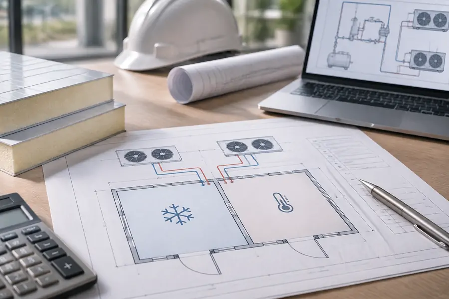
Compare These Lines on the Supplier’s Drawing
Instead of accepting “one unit is cheaper,” request a side-by-side technical schedule showing:
| Required Information | Why It Changes the Decision |
| Cooling capacity in kW at each zone’s design conditions | Confirms the actual medium- and low-temperature duty |
| Compressor count, circuit diagram, and suction pressures | Reveals whether the cooler load is forced onto freezer suction |
| Minimum stable capacity and staging method | Shows what happens when only one zone needs cooling |
| Defrost sequence and control schematic | Exposes interactions during freezer defrost |
| Line lengths, ambient rating, and condenser ventilation | Checks performance at the real installation site |
| Electrical separation, alarms, and repair access | Makes single-point failures visible |
| Installed cost and modeled annual kWh | Compares ownership cost, not just purchase price |
The enclosure should be specified alongside the refrigeration. LINBLE’s PU/PIR cold room panels are offered from 50 to 200 mm, with a listed thermal conductivity of ≤0.024 W/(m·K). Properly sized partitions and sealed joints limit heat transfer between zones, but insulation cannot correct an inefficient compressor arrangement.
Choose the Circuit Layout Before Finalizing the Quote
For a conventional two-compartment walk-in cooler and freezer, begin with independent medium- and low-temperature refrigeration. Consider a shared package only when drawings establish genuine circuit independence or an engineered multi-suction design, and when its lifecycle cost justifies the complexity.
LINBLE provides custom cold rooms, matching condensing units, evaporators, and insulated enclosures for different temperature zones.
Share your compartment dimensions, products, target temperatures, loading schedule, ambient conditions, and available installation space through the LINBLE contact page to assess whether a shared refrigeration arrangement is feasible or two independent systems are the better fit.