
Cold room defrost control coordinates several events: starting defrost, ending it, allowing meltwater to drain and returning the evaporator to normal cooling. Defrost termination, drip time and fan delay have different jobs. Understanding that sequence helps owners describe a problem and request a useful commissioning record without treating every pause as a failed component.
The details depend on the evaporator, defrost method and controller. This guide explains the sequence and the questions to ask; it does not provide universal temperatures, timings or wiring instructions. Use the manual for the installed equipment when checking or changing its settings.
Read Defrost As A Sequence
In a typical controlled electric-defrost sequence, normal refrigeration gives way to defrost, heat is applied, defrost ends, water is allowed to drain and cooling resumes with the fan managed according to the design. The transitions are as important as the heating period. A sequence should be understood before individual parameters are adjusted.
Air-defrost systems have a different arrangement and may use different fan behaviour. Do not transfer an electric-defrost sequence to another method without checking its documentation. The controller display, evaporator model and wiring information should all refer to the same installation.
Our comparison of water and electric defrost discusses the heat-source choice. Here the focus is the control sequence: what happens, what ends each stage and what evidence an operator should record.
Defrost Initiation: What Starts The Cycle?
Start by identifying the initiation method from the equipment manual and commissioning record. It may be a schedule, an interval, a demand-based function or a manual request, depending on the control. An operator should know which is used before assuming that the cycle always begins at the same wall-clock time.
For example, the Heatcraft Beacon II manual describes interval timing from power application and a delayed first start. That is a model-specific example of why an interval controller should not automatically be interpreted as a calendar-style timer.
Ask the commissioning technician to explain the expected behaviour after a power interruption. Record how the controller returns to its normal sequence and whether operators need to do anything. Keep that information with the operating instructions, rather than relying on memory from installation day.
Defrost Termination: What Ends Heating?
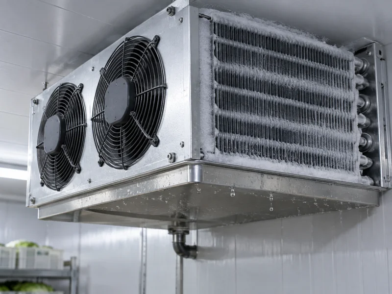
Termination is the condition that ends the active defrost stage. Depending on the control, that can involve a temperature sensor, elapsed time or another specified logic. It is separate from the room’s normal cooling setpoint.
The Heatcraft electronic-control manual describes temperature termination with a maximum duration, as well as other supported modes. Its parameters belong to the documented control family; they are not default instructions for all cold rooms.
For your own installation, ask what is intended to end a normal cycle and how the technician will verify that it happened. Have the sensor location documented. A setting written in a notebook is difficult to interpret if nobody knows which sensor supplies the measurement.
Drip Time: What Happens After Defrost Ends?
Drip time provides a defined stage for meltwater drainage before the next part of the sequence. In the cited electronic-control example, it holds the compressor and evaporator fans off for a programmed period. Other designs must be checked against their own documentation.
From an owner’s perspective, the useful question is whether the drain stage completes as intended. Ask the technician to inspect the drainage arrangement as part of commissioning. A controller setting alone cannot establish that water is actually leaving the evaporator and drain pan correctly.
Record the visible symptom carefully if water remains. Note whether it is in the pan, at the outlet, on the floor or around another part of the room. Those observations help separate drainage questions from assumptions about how long defrost should run.
Fan Delay: Why Cooling And Airflow May Not Restart Together
Fan delay manages the return of evaporator airflow after defrost. Depending on the equipment, it can involve temperature-dependent logic, a timed stage or a combination of controls. A stationary fan immediately after defrost is therefore not automatically a motor failure.
Heatcraft’s unit-cooler installation manual includes a combined fan-delay and defrost-termination control for specified equipment. That example illustrates the need to check the installed control arrangement before interpreting fan operation. Its model-specific values should not be copied into a different system.
Ask the technician to identify the condition that releases the fans and any protective limits. Put the explanation into the handover record. Operators then have a basis for reporting “the fan did not restart after the expected condition” instead of simply reporting that it stopped.
Keep These Four Concepts Separate
| Control function | Question it answers | Useful commissioning record |
| Initiation | When does defrost begin? | Schedule, interval or other initiating logic |
| Termination | What ends the active defrost stage? | Normal end condition and any maximum duration |
| Drip stage | How is drainage allowed before recovery? | Specified stage and observed drainage |
| Fan restart | When is evaporator airflow restored? | Release condition and observed restart |
Use the table as a discussion worksheet, not as a programming guide. Some controllers combine functions or use different names. Have the installer translate the actual parameter names into these operating questions.
Where more than one evaporator is installed, ask how the controls coordinate the individual units. Record whether the sequence is shared or independent. An explanation based on only one unit may not describe the whole room.
Observe A Complete Cycle Before Describing The Problem
When an issue is intermittent, a short observation log can be more useful than an isolated photograph. Record when the cycle began, what the display showed, when defrost ended and when normal airflow returned. Note the room’s loading and door activity during the same period.
Take photographs only from safe, accessible positions. Do not remove covers or approach moving or energised components to obtain evidence. The technician should perform the electrical and refrigeration checks needed for diagnosis.
A complete observation also reduces misunderstandings about temperatures. Ask which sensor is shown on the display and whether the controller changes its displayed value during defrost. Keep an independent monitoring record where your operating plan requires one.
Use Symptoms To Ask Better Questions
The Fan Is Stopped After Defrost
Record the time since defrost ended and the controller indication. Ask whether the observed state matches the programmed fan-release condition. Let the technician distinguish a normal delay from a sensor, output or motor problem.
Water Appears Around The Evaporator
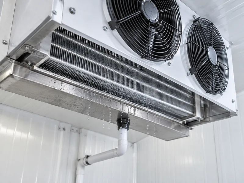
Photograph the location and note when it appeared in the sequence. Ask for a review of drainage and the relevant control stages. Avoid changing several settings at once before the original condition has been documented.
The Room Takes Too Long To Recover
Record the starting conditions, incoming product and door use. Ask the technician to compare the sequence with the intended operation and assess other possible contributors. Our article on temperature fluctuations in cold rooms covers related investigation points beyond defrost.
Ice Returns Repeatedly
Keep a dated record of where it returns and how quickly. Ask for a diagnosis that considers the actual installation rather than only adding time to a cycle. The aim is to identify the reason, then verify the correction under representative conditions.
Prepare A Settings Record That Survives Staff Changes
Record the controller model, software or manual revision where available, evaporator model and defrost method. Add the date, technician’s name and reason for each adjustment. Photograph the final settings screens if the service procedure and site policy permit it.
For each important parameter, write both the actual name shown by the controller and a plain-language explanation. Include the units. This helps prevent a later operator from confusing a temperature threshold with a time period or a normal setting with a protective limit.
Keep the previous approved settings as part of the service history. If a change makes operation worse, the technician has a clear record of what changed. Avoid undocumented trial-and-error adjustments by several people.
Include Alarms In The Handover Discussion
Ask how temperature alarms behave during and after defrost and how operators can recognise a genuine problem. The answer should come from the installed controller documentation and the site’s monitoring requirements. An alarm delay should not be treated as proof that product conditions are acceptable.
Agree who receives notifications and what happens if the first person does not respond. Test the agreed notification route during commissioning where supported. A correctly displayed alarm is only one part of an effective response.
Our guide to cold-room temperature monitoring discusses the broader monitoring role. Keep the monitoring and defrost records together so unusual events can be reviewed in context.
Specify Control Functions When Ordering An Evaporator
When requesting a cold room evaporator, provide the room duty, refrigerant arrangement, proposed defrost method and existing controller details. Ask which sensors and controls are supplied with the unit and which must be provided elsewhere. Request a coordinated equipment proposal rather than assuming every required function is included.
For replacements, provide the original wiring and equipment documents if available. Ask the installer to review compatibility before the equipment arrives. A new evaporator does not automatically share the old unit’s sensor arrangement or control behaviour.
LINBLE’s cold room accessories can be considered as part of the wider specification, with exact functions and model suitability confirmed for the project. Keep the quotation specific about what is supplied, installed, programmed and tested.
What A Useful Commissioning Handover Includes
- Equipment identity: Controller, evaporator and relevant sensor details.
- Sequence description: Initiation, termination, drainage and fan-restart logic.
- Settings record: Approved values, units and the applicable manual.
- Observed operation: A completed cycle with any issues recorded.
- Monitoring: Display behaviour, alarms and the agreed response route.
- Support: The service contact and information to provide with a fault report.
Ask for this record when the room is commissioned and update it after relevant service work. It gives staff a practical explanation of the pauses and transitions they see. More importantly, it gives the service team evidence to work from when the sequence no longer behaves as expected.