
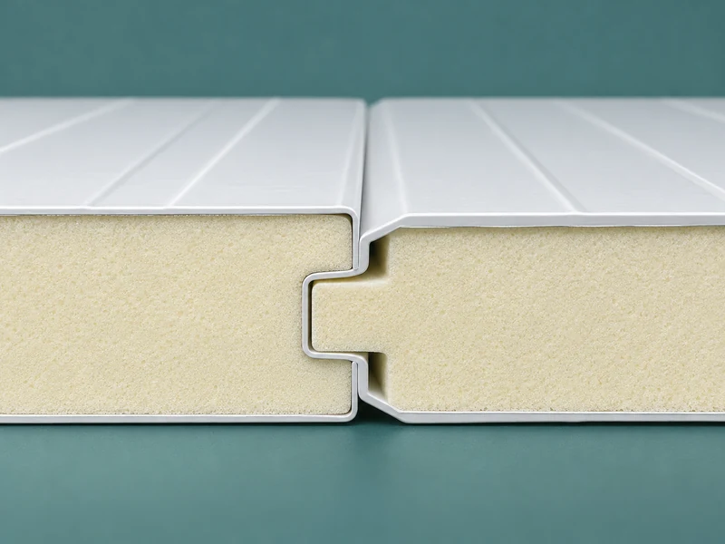
Cold room insulation foam in a factory panel reduces heat flow through the panel area. Joint sealing closes the paths where assembled parts meet, so warm, moist air cannot freely reach cold surfaces. On a LINBLE room, review the core specification and the joint detail separately, then verify that the two work together at corners, openings and other transitions.
What Does the Panel Foam Do Across the Wall?
The rigid core forms part of the sandwich panel between its metal skins. The core, thickness and construction influence heat flow through the panel field. The skins and joining system also have to suit the intended assembly, exposure and finish.
LINBLE lists PU and PIR options in its cold room panel range, with different thicknesses and cam-lock or plug-in assembly depending on the panel type. The designer needs the selected panel data and thickness for the room conditions. Use the panel specification guide to check what a core description alone leaves open, including facing and joint information.
Buying a thicker panel can change the heat flow through an intact section. It has little bearing on an installation gap where two edges fail to meet. That gap needs its own review even when the wall field is performing as selected.
What Does the Joint Have to Do?
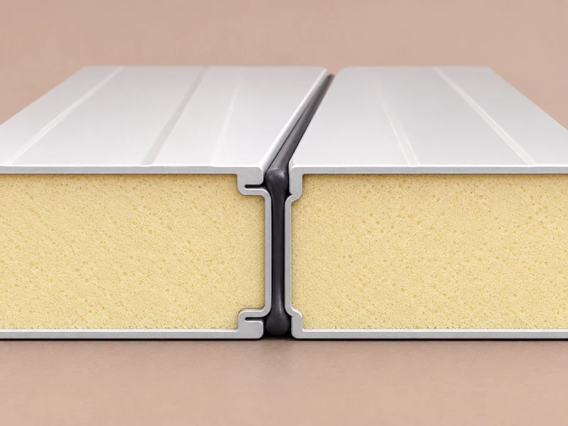
A joint has to bring adjacent panels together and preserve the intended air and vapor control at that connection. A seal may sit within the profile or be applied at a specified face. Its position, continuity and compatibility with the adjacent materials matter as much as the name of the sealant.
The ASHRAE refrigerated-facility design chapter describes the importance of maintaining the air and vapor envelope across junctions in cold construction. In a modular room, follow the project detail around the floor edge, across the ceiling connection and back down the corner. A continuous-looking line on the inside face may be a hygiene finish while the main control layer is detailed elsewhere.
| What You Are Looking At | Its Job in the Assembly | What to Verify |
| Rigid panel core | Limit heat flow through the insulated field | Specified core and thickness for the selected panel |
| Mating panel edges and locks | Bring adjacent panels into the designed fit | Correct engagement, support and alignment |
| Gasket, tape or sealant at the joint | Close the specified air and moisture path | Approved material, location and continuous contact |
| Local insulated infill where detailed | Close an approved void in a junction | Required depth and connection to the surrounding seal |
When Is Field Foam Part of the Detail?
Use it when the approved assembly calls for an insulated infill and specifies how it is protected and sealed. On some details, filling a cavity helps limit a local heat path. The surrounding closure still needs to make the required connection to the panel skins or specified control layer.
Before using a general expanding product, ask whether its cure, expansion, adhesion and exposure suit the joint. Excess expansion can affect a fit or make later trimming harder, and a bead applied to wet or dirty metal may have poor contact. Where a rated assembly is involved, use the detail required for that assembly.
Why Does a Cam-Lock Joint Need Its Own Installation Check?
The lock brings the edges together. The supplier’s profile and seal detail determine what happens when they meet. A lock that feels tight can still leave an uneven joint if the panel edges were damaged or the first panel was set against an uneven support.
Ask for the fitting sequence and tolerances for the selected panels. In a plug-in assembly, establish when the installer applies any specified seal and how the edges are checked as the run progresses. In either system, inspect the first corner and first straight joint before the same technique is repeated across a whole room.
Keep the material samples or product references with the job. If a local repair is needed years later, knowing the panel system and original joint treatment saves a second investigation behind trim that may still be serviceable.
How Do You Investigate a Wet Line Along a Panel Joint?
Start by locating the moisture and recording when it occurs. A straight line at the vertical seam during humid weather is different from water that runs down from a pipe above the ceiling. A photo of the entire run and a close view at the point where the line starts can help separate the two.
Check the panel fit before covering it with another bead. LINBLE’s guide to floor levelness and panel joint fit explains how the base affects alignment higher up the wall. If one panel stands proud or the seam changes width with height, ask the installer to check the engagement and support against the approved drawing.
Can a Surface Temperature Reading Identify the Cause?
It helps narrow the inspection when you compare the seam and the adjacent wall under similar conditions. A colder band could indicate a local thermal bridge, while irregular dampness can also point to air leakage or water from elsewhere. Measurements on reflective skins can mislead unless the method accounts for the surface and operating conditions.
Record the room and adjacent temperatures, the state of the doors and whether the symptom follows washdown or a busy shift. If a ceiling seam is wet near an evaporator, check the drainage and service penetrations too. A repair aimed at the panel core is premature while water could be entering from a nearby assembly.
Trace the visible pattern through an operating cycle. A seam that becomes wet when the adjacent dock opens suggests a different inspection than a ceiling line that appears after every defrost. Give each observation a timestamp so the installer can compare it with equipment and room activity.
What Should LINBLE and the Installer Agree Before Assembly?
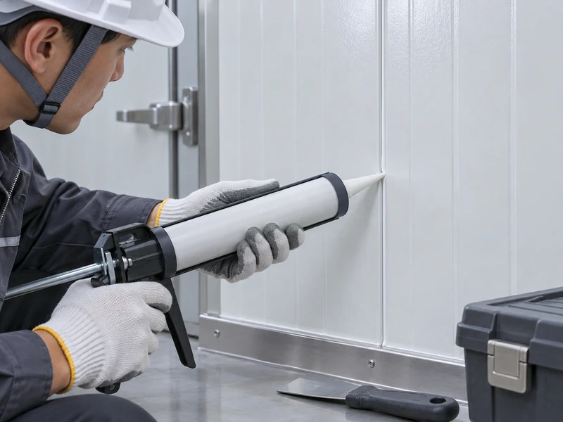
Approve the panel schedule and the joint details together. Show the start and end of each sealing run, the prep required at the contact surfaces and when the work will be inspected. For a LINBLE modular cold room, the installation sequence should leave access to the parts that become hidden as adjoining panels and trims go in.
Take a freezer wall that meets a ceiling over a humid production area. The installer can make the visible internal corner neat after all panels are in place, yet the outer junction may already be hidden by structure. A pre-close inspection gives the responsible team a chance to verify the intended connection while it can still be reached.
Use a simple hold point for unusual corners, door frames and repaired joints. Photograph the open condition, verify the selected materials and record the finished detail. Include these records in the cold room commissioning checklist so later maintenance can trace what is behind the trim.
Which Information Helps When You Ask for a Repair Detail?
For a repair enquiry, identify the installed panel from its order records, include the thickness and edge profile, and pair an overall seam photo with a close view from each face you can safely reach. Describe the age of the seam, any recent repair and the temperature and moisture conditions when the problem appears. State whether the room is still operating, since access and allowable work may differ during a planned shutdown.
Where a joint has opened, establish whether the panels need to be reseated or the support repaired before selecting a sealant. Where the panels fit as designed, the repair can focus on the specific layer or closure that has failed. The repair is complete when the relevant connection is restored and checked in service, with the new detail recorded for the next inspection.