
A cold bridge is a weak point where heat bypasses the freezer room’s insulation. It often appears where insulation is interrupted, compressed, poorly joined, or penetrated by a conductive material.
Cold bridges can lead to frost, condensation, higher energy consumption, unstable room temperatures, and gradual damage to building materials. Preventing them requires more than choosing thicker insulated panels. The entire freezer room must be treated as one continuous thermal envelope.
Why Cold Bridges Form in Freezer Rooms
Heat naturally moves from warmer areas toward colder areas. In a freezer room, the temperature difference between the interior and exterior creates constant pressure for heat to enter through walls, ceilings, floors, doors, and structural connections.
Most insulated surfaces slow this heat transfer effectively. Problems begin when a conductive route allows heat to bypass the insulation.
Common examples include:
- Metal fasteners passing through insulated panels
- Gaps between wall and ceiling panels
- Poorly sealed panel joints
- Steel frames connected directly to internal surfaces
- Uninsulated floor edges
- Door frames without thermal breaks
- Pipes, cables, and drains penetrating the enclosure
- Damaged or incomplete vapor barriers
A cold bridge may initially appear to be a small construction defect. In practice, it can affect a much larger area because moisture, frost, and repeated temperature changes gradually weaken nearby joints and materials.
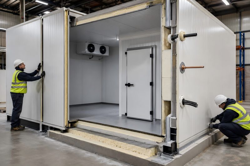
Maintain a Continuous Thermal Envelope
Continuous insulation is the foundation of effective freezer design. Insulation should form an uninterrupted enclosure around the freezer room, including the walls, ceiling, floor, corners, doors, and service penetrations.
It is not enough to evaluate each component separately. A wall panel may have excellent insulation performance, but its advantage is reduced when the wall-to-floor connection contains exposed concrete or steel.
Designers should review every point where different building elements meet. These junctions usually present a higher cold-bridge risk than the center of an insulated panel.
Key junctions include:
- Wall-to-wall corners
- Wall-to-ceiling connections
- Wall-to-floor connections
- Freezer room junctions with the building structure
- Openings for refrigeration pipes and electrical cables
Detailed junction drawings should be completed before construction begins. Solving these connections during installation often results in improvised sealing methods that are difficult to inspect and maintain.
Select Insulated Panels Based on the Full Assembly
Insulated sandwich panels are commonly used for freezer room walls and ceilings. Their cores may be made from polyurethane, polyisocyanurate, or other insulating materials.
Joint design, panel edge shape, locking method, facing material, and installation accuracy also influence thermal performance.
A thick panel with a poorly formed joint can create more heat leakage than a slightly thinner panel with a precise interlocking connection.
Cam-lock or tongue-and-groove systems can help maintain alignment and reduce joint gaps. However, the connection must be tightened correctly. Excessive force may compress the insulation, while insufficient tightening can leave open spaces that allow air and moisture to enter.
Panel joints should also be positioned carefully. Long, continuous joints exposed to high temperature differences require reliable sealing and should remain accessible for inspection whenever possible.
Design Wall, Ceiling, and Floor Connections Carefully
The junction between freezer room surfaces is one of the most common locations for cold bridges.
At wall-to-ceiling connections, the insulation layers must overlap or connect without leaving an exposed structural route. Ceiling panels should not simply rest against wall panels with sealant filling the remaining gap.
At wall-to-floor connections, concrete can transfer heat into the freezer if the floor insulation stops at the wall line. Floor and wall insulation should join seamlessly to maintain a continuous thermal barrier.
Corners require similar attention. Internal and external trims may improve appearance, but decorative covers do not replace insulation. Any empty space behind the trim should be filled with a suitable insulating material and sealed against moisture.
The table below summarizes several high-risk junctions and practical prevention methods.
| Construction Area | Common Cold-Bridge Cause | Recommended Prevention |
| Wall-to-ceiling joint | Misaligned panels or incomplete insulation contact | Use overlapping insulation details and seal the full joint depth |
| Wall-to-floor joint | Floor insulation ends before reaching the wall | Connect floor insulation directly to the wall panel insulation |
| Internal corner | Open cavities behind metal trim | Fill cavities with compatible insulation and seal both sides |
| Door opening | Conductive frame connected to external steelwork | Use a thermally broken frame and insulated threshold |
| Pipe penetration | Oversized opening filled only with sealant | Install an insulated sleeve and seal the vapor barrier continuously |
| Structural connection | Steel members cross the insulated enclosure | Separate internal and external steel with thermal-break materials |
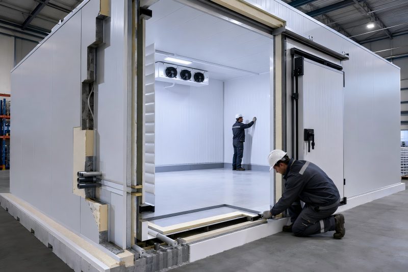
Prevent Cold Bridges Through the Freezer Floor
Floor construction is often more complicated than wall construction because it must support equipment, shelving, pallets, and moving loads.
A typical freezer floor may include a structural slab, vapor barrier, insulation, heating system, reinforced topping slab, and protective finish. Coordinate all layers to control heat transfer and moisture.
The insulation should be strong enough to resist compression under operational loads. When insulation is crushed, its thickness decreases and its thermal resistance is reduced.
The floor perimeter deserves special attention. If the insulated floor meets an uninsulated wall foundation, heat can travel through the concrete and create frost along the room edges.
The floor insulation should extend to the wall insulation without interruption. In some projects, an insulated upstand is installed around the perimeter to separate the cold floor from the surrounding structure.
Low-temperature freezer rooms may also require underfloor heating or ventilation to prevent the soil and supporting slab from freezing. This system should be designed without creating conductive paths through the insulation.
Use Thermal Breaks Around Structural Steel
Steel transfers heat quickly and is therefore a major cold-bridge risk. Structural frames, brackets, ceiling supports, and door reinforcements should not pass directly from the warm side to the cold side.
Where structural connections are necessary, thermal-break components should be added. These may include rigid insulating blocks, non-metallic spacers, composite plates, or specially designed connection systems.
The correct solution depends on the load and location. A thermal-break material must provide insulation while still supporting the required structural force.
Simply covering exposed steel with foam is often insufficient. The steel may continue through the insulation and transfer heat beneath the surface. The connection itself must be interrupted or separated.
Where possible, heavy structural frames should remain outside the insulated enclosure. Internal equipment can then be supported using independent structures designed to minimize contact with the external building frame.
Install Doors With Insulated Frames and Thresholds
A freezer door is a moving part of the thermal envelope, making it more difficult to seal than a wall panel.
Cold bridges often develop around door frames, hinges, tracks, thresholds, and mounting brackets. Metal components may connect the interior directly to the warmer exterior.
Freezer doors should use insulated leaves, thermally broken frames, flexible gaskets, and suitable edge heaters when required. The door frame must connect continuously with the wall insulation.
The threshold is especially important. A metal threshold installed directly across the floor opening can become a strong thermal bridge. Insulated or thermally separated threshold designs should be used.
Door heaters reduce gasket frost but cannot replace proper construction. Excessive reliance on electrical heating increases operating costs and can hide an underlying insulation defect.
The door opening should also remain square and level. Misalignment creates uneven gasket pressure, allowing warm air to enter even when the insulation details are correct.
Seal Pipe, Cable, and Drain Penetrations
Every penetration creates a break in the insulated enclosure. Refrigeration pipes, electrical conduits, lighting cables, sensors, drainage lines, and fire protection systems must be planned before panels are installed.
Unplanned openings are often cut on-site and filled with sealant or expanding foam. This approach may close the visible gap but fail to restore the insulation and vapor barrier properly.
A better penetration design includes:
- A correctly sized opening
- An insulated sleeve
- Compatible insulation around the service line
- An airtight interior seal
- A continuous exterior vapor seal
- Enough flexibility for pipe movement and thermal expansion
Refrigeration pipes should be insulated continuously through the wall or ceiling. The insulation should not stop at the panel surface.
Pipes can expand and contract during operation. A rigid seal may crack over time, so penetration systems should allow limited movement without opening a path for warm, moist air.
Maintain Vapor-Barrier Continuity
A cold bridge and a vapor-barrier defect are different problems, but they often appear together.
The vapor barrier is typically to stop moisture in the surrounding air from moving toward the cold interior.
When the vapor barrier is damaged, moisture can enter panel joints or insulation layers. Once this moisture reaches a cold surface, it may condense or freeze.
Wet insulation performs poorly, which increases heat transfer and makes the cold bridge more severe. Freeze-thaw cycles can weaken sealants and loosen panel joints.
The vapor barrier should remain continuous around corners, penetrations, door frames, and floor junctions. Seal overlaps with compatible materials instead of depending solely on pressure.
During installation, sharp edges, screws, and panel movement should be controlled to prevent accidental punctures.
Control Fasteners and Metal Trims
Fasteners are necessary for securing panels and accessories, but each metal fastener can create a small conductive route.
The number, length, and position of fasteners should follow the panel system requirements. Unnecessary screws should be avoided, especially when they pass through the full insulation thickness.
Fasteners may require insulated washers, protective caps, or concealed installation methods. The exact method should match the panel supplier’s structural and thermal recommendations.
Metal trims should be used carefully. They provide protection and improve the appearance of joints, but a continuous metal strip can connect warm and cold surfaces.
Trims should not bypass the insulation layer. Where metal covers are necessary, they should be installed on one side of the thermal envelope or separated with insulating material.
Improve Installation Quality Control
Many cold bridges are caused by small installation errors rather than major design failures.
Panel edges may be damaged during transport. Sealant may be applied unevenly. Locking systems may not be fully engaged. Openings may be cut larger than required. Insulation may be removed to make room for brackets or pipes.
These issues can be reduced through staged inspections.
Before closing each junction, installers should confirm that:
- Insulation is continuous
- Panel joints are clean and fully engaged
- Sealant covers the complete joint
- Vapor barriers overlap correctly
- Penetrations are insulated and sealed
- Fasteners do not create unnecessary conductive paths
- Damaged panel edges have been repaired
Photographic records can be useful because many critical details become hidden after trims, flooring, or ceiling finishes are installed.
Test the Freezer Room Before Full Operation
Visual inspection alone may not reveal every cold bridge.
After installation, the freezer room should be cooled under controlled conditions and checked for abnormal surface temperatures, condensation, air leakage, or frost formation.
Thermal imaging reveals heat leaks at joints and structural connections. Smoke testing or controlled pressure testing can help locate air leakage around doors and panel seams.
Testing should assess more than whether the room reaches its target temperature. A refrigeration system may overcome construction defects by running longer, but this does not mean the enclosure is performing correctly.
Compressor operating time, surface temperature patterns, door-frame frost, and temperature recovery after door openings can provide additional information about enclosure quality.
Avoid Solving Design Problems With More Refrigeration Capacity
An oversized refrigeration system cannot permanently correct cold bridges.
Additional capacity may lower the room temperature, but the system will still consume more energy and may experience frequent cycling, uneven temperatures, or excessive frost.
The more reliable approach is to reduce the cooling load before increasing equipment capacity. This means improving insulation continuity, air sealing, door performance, and penetration details.
Refrigeration equipment should be selected for the actual room load, including product load, door openings, lighting, personnel, and expected heat transfer. It should not offset preventable flaws in freezer room construction.
Plan for Inspection and Future Maintenance
Freezer room joints and seals change over time. Panels may move slightly, gaskets may harden, sealants may shrink, and equipment installation may create new penetrations.
Areas with a high risk of cold bridging should remain accessible where practical. Service pipes should not be hidden behind permanent finishes without inspection points.
Routine checks should focus on:
- Frost around corners and door frames
- Condensation on external surfaces
- Cracked or separated sealant
- Damaged panel facings
- Loose door gaskets
- Wet flooring near thresholds
- Unusual compressor operating patterns
- Newly installed cables or pipes
Early repair is usually simpler than correcting moisture damage after it spreads through insulation or structural materials.