
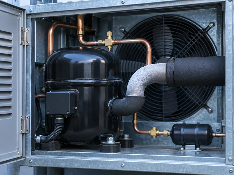
When a cold room compressor or its suction line appears to be icing up, start with the frost location and the point in the operating cycle when it appears. A patch on exposed copper can simply mean that moist air is contacting a cold surface. Frost spreading toward the compressor deserves a closer look, and a technician needs operating measurements to determine whether liquid refrigerant is returning.
Where Does the Frost Begin?
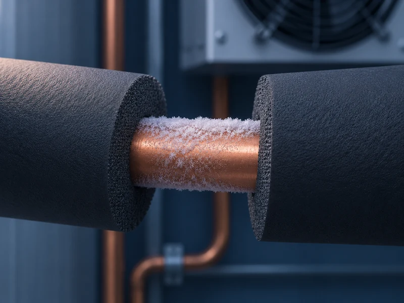
Photograph the outside of the equipment from a safe position and record the first visible frost. A short patch at a damaged section of insulation tells a different story from frost that advances toward the inlet during operation. Compare those photos with the room temperature, time since defrost and whether the evaporator fans are running as expected.
LINBLE’s cold room condensing unit range includes several boxed layouts. Ask for the supplied model and piping drawing so a service technician can identify the suction connection and the components upstream of it. Frost near a cabinet entry could form where pipe insulation ends, even when the refrigerant has enough superheat at the compressor.
Why Can Frost Form on a Line Carrying Vapor?
A surface below freezing can collect frost in humid air even when the refrigerant inside the tube is fully vapor. Refrigerant temperature, pressure and the outdoor moisture conditions all affect what you see. Surface frost therefore cannot establish the state of the refrigerant by itself.
Inspect accessible insulation for a split seam, damaged vapor seal or an exposed fitting. A pattern that repeats at the same small gap, with normal room performance, makes the insulation an obvious item to check. If the pattern changes, record the progression for the technician instead of assuming the original explanation still applies.
Which Frost Patterns Warrant Different Checks?
Use the pattern to decide what data to collect. Match it to the load, fan and defrost sequence before considering an intervention. The table describes inspection leads for a qualified service team.
| Visible Pattern | What to Record | What the Technician Can Check |
| Frost confined to one uninsulated joint or bend | Location, surrounding humidity and whether the patch grows | Insulation condition and normal running data |
| Frost spreads along the suction run toward the compressor | Timing, room temperature and whether load is steady | Suction pressure and temperature together, and evaporator feeding |
| Frost appears with poor airflow and visible evaporator ice | Fan behavior, last defrost and room recovery | Coil airflow, defrost completion and drainage |
| Frost or abnormal noise appears on restart | Shutdown duration and first minutes after restart | Startup behavior, migration risk and approved protective devices |
Frost at the evaporator can change the rate at which air reaches the coil. An airflow problem and a refrigerant feed issue can occur together. Use LINBLE’s evaporator icing and defrost checks to describe the coil symptom separately from any frost observed at the outdoor unit.
What Does the Timing Tell You?
Note whether frost appears in steady operation, after the room has reached its target, or immediately after defrost and restart. These states can put different loads on the coil and controls. Comparing a startup reading to a stable design selection may hide the condition that matters.
For example, a thin patch that stays at the cabinet entry through several cycles is useful evidence for an insulation inspection. A pattern that appears only during restart and coincides with abnormal knocking or repeated trips warrants prompt assessment under the site’s service procedure. Leave covers and refrigerant circuits to authorized personnel.
How Can a Technician Check for Liquid Return?
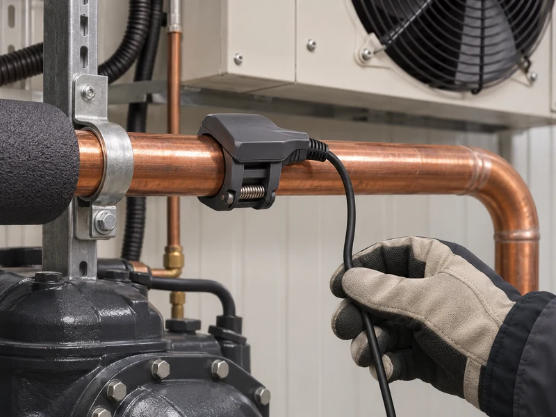
Compare the measured suction-line temperature with the saturation temperature corresponding to the measured suction pressure at the same location, using the correct refrigerant data. The difference is suction superheat. For zeotropic blends, use the appropriate dew-point convention when evaluating vapor superheat.
Evaporator outlet superheat describes conditions at the coil outlet, while compressor inlet superheat reflects what reaches the compressor after the suction run and any intervening components. The ASHRAE refrigeration systems chapter discusses suction piping, insulation and protection from liquid return. Interpret the values against the equipment’s operating limits and the conditions at the time of measurement.
Why Is One Reading Usually Incomplete?
A single measurement can miss a problem that occurs at restart, minimum load or just after defrost. Record pressure, line temperature, room temperature and relevant control states as close together in time as practical. The technician can compare repeat readings during stable operation and the part of the cycle associated with the symptom.
When checking the LINBLE cold room evaporator, record fan state and coil condition as well. An overloaded or obstructed room can change airflow around the coil, while a control fault can change when fans restart. Compare what is observed with the selected equipment and its actual sequence.
What Does the Same Frost Mean at Two Different Pressures?
Take a simplified example in which the technician measures a suction line at −4 °C. If the measured suction pressure corresponds to a saturation temperature of −14 °C for the refrigerant at that point, the calculated superheat is 10 K. If that pressure instead corresponds to −5 °C, the same pipe temperature gives 1 K.
In either situation, the metal could be cold enough for exterior frost to appear. The two calculations tell the service team different things about the vapor margin at the measurement location. The numbers illustrate the calculation and need to be interpreted against the selected equipment and measurement accuracy.
Check that pressure and temperature represent the same section of pipe. Mixing a pressure from one side of a suction component with a temperature from another can distort the result. On a system with a long run, the temperature at the coil outlet and at the compressor inlet can differ even during a stable cycle.
What Should Be in the Service Report?
Include equipment model, refrigerant, room setpoint, outside conditions, frost photos and the operating stage of each reading. Note which side of any suction component the measurement came from, and include the room’s previous stable readings if available. This is enough to give the technician a starting point without turning a photograph into a diagnosis.
Ask the operator when the symptom first became visible and what else changed that week. A door that now stays open during replenishment, a recently replaced fan or new shift hours can all change the conditions under which an old unit runs. Put those observations beside the measurements so the service team can choose which operating state to reproduce.
The original LINBLE condensing unit selection data can help identify which conditions were used for the design. Compare those assumptions with current usage and recent changes such as new racking, altered door traffic, or changes to coil or controls. A system that behaved well before a change in use may need a different investigation from one that has shown the same symptom since startup.
When Should the Team Recheck the Room?
After authorized service, observe the room through the cycle that produced the symptom and record the result. Confirm cooling recovery, normal fan and defrost sequence and the location of any remaining surface frost. LINBLE’s commissioning checklist provides a useful place to organize this evidence with the equipment record.
Avoid changing charge or valve settings on the strength of frost alone. A clear description of where frost starts, when it moves and what the system was doing at the time allows the service team to separate a local insulation issue from a refrigeration fault.